

Trending
Opinion: How will Project 2025 impact game developers?
The Heritage Foundation's manifesto for the possible next administration could do great harm to many, including large portions of the game development community.
Featured Blog | This community-written post highlights the best of what the game industry has to offer. Read more like it on the Game Developer Blogs or learn how to Submit Your Own Blog Post
Players talk to your game through the language of a controller and the translation can be messy. If you can make an accurate translation, you can make a tight controlling game.

When a game supports controllers, the player is likely using an analog stick at all times. Nailing the input processing can have a substantial impact on quality throughout the experience. Let’s walk through some core concepts along with examples from INVERSUS.
Before tuning the analog stick, you need to know how it works. What is the hardware actually reporting when you move the stick around? Here’s what the stick inspection for INVERSUS looks like. I don’t claim this to be the best possible display, but all the conveyed information is important.
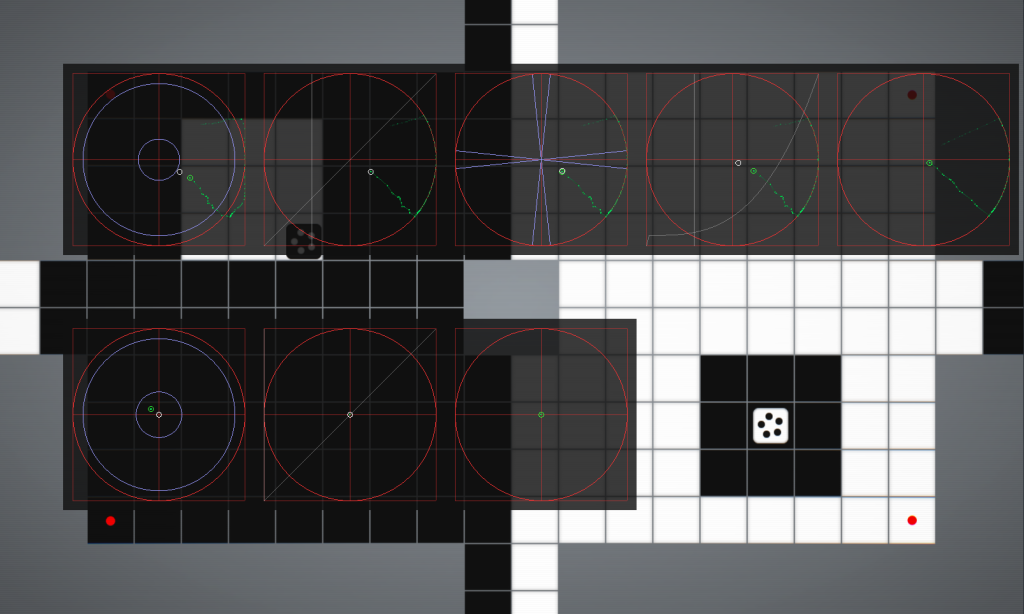
Before I cover each part in detail, let me present a high level overview. I was using an Xbox 360 controller attached to a PC. The top row represents stages of processing on the left stick. The bottom row is the right stick. You’ll notice that the top row has more data on display than the bottom row. This is because INVERSUS only uses the left stick and it gets special treatment. I’ll only talk about that top row from hear on, but everything still applies to the right stick for games that use it.
The first two circles represent operations that convert from specific hardware (e.g. an Xbox 360 controller or a DualShock 4 controller) to a common input space. Different hardware is different. It is mechanically different and it feels different. This is a rather obvious fact to state, but it might be one you haven’t considered.
Let’s say you develop your game on console A and later port it to console B. You’ll want to maintain the quality bar of your original tuning. If the analog sticks behave differently, things will feel slightly off. The idea is to convert the x,y values from the supported hardware spaces into a common game space. The game layer can now be tuned agnostic to the controller type.

The first stage represents radial dead zone processing. The hardware may report bad values due to limitations in construction or wear and tear from usage. This stage removes said unreliable values from the game.
So what are we looking at? The red square bounds a coordinate system with (-1,-1) at the bottom left and (1,1) at the top right. It is divided into quadrants along the X and Y axes. The bright red circle is the unit circle. These guidelines remain the same for each the following stages.
The small green circle is the input value. Because this is the first stage, these are the raw values directly form the hardware. The green trail shows a recent history of inputs (green dots) connected by line segments. The small white circle is the processed output of the stage.
Unique to this stage, we have two more circles: the inner dead zone and the outer dead zone.

Values within the inner circle cannot be trusted. This is the inner dead zone. In the image, I am gently moving the stick around an area that isn’t receiving any resistance. The stick will not be pulled back to dead center here. With controller age and abuse, this area will grow, shift and distort.
Every value within the inner dead zone is mapped to zero, giving us a reliable origin point for the game logic. You’ll notice that the white output circle remains locked to the center at all times. If the inner dead zone is too tight, motion can drift as the stick comes to rest outside.
Hardware vendors often provide a recommended inner dead zone value. This is a good place to start, but you should do your own testing across as many controllers as you can get your hands on. These recommended values might not be perfect and it never hurts to verify with hard data.

Values outside the outer circle cannot be trusted. This is the outer dead zone. Most games do an acceptable job with the inner dead zone, but you can likely find errors due to a poor (or nonexistent) outer dead zone.
In the first image, I am moving the stick straight up to the top edge and sliding it counterclockwise around the edge. At the top, it reports values on or outside the unit circle. Life isn’t perfect and this is expected. As I roll the stick left, however, it actually cuts within the unit circle for a bit before extending back out. This behavior isn’t common to all controller types, but it can happen on Xbox 360 controllers.

Based on this data, you might assume the left side is just inaccurate, but it’s not so simple. In this second image, I first move the stick directly left. In this case, it reports as expected. It is only after rotating it in a circle that we see the error.
If the error only happens after rotation, how important is it? It could be very important depending on the game. Imagine a game where the stick magnitude controls player speed. If the player character moves up and banks left, it will be moving slightly under max speed until the stick is released and extended again.
Every value outside the outer dead zone is scaled to have a magnitude of one. This creates a reliable unit circle for game logic. Notice that the output (white circle) remains locked to the edge.
Unfortunately, there likely aren’t any recommended values for the outer dead zone. Once again, perform your own tests and visualize the data. Plug in a bunch of controllers and see how they react. There might be subtle inaccuracies after complex motions that your game needs to account for.
With the inner and outer values snapped to zero and one respectively, what do we do with intermediate values? In order to avoid any discontinuities, we linearly interpolate their scale. The resulting logic might look like this:
void ApplyRadialDeadZone
(
    float* pOutX,      // out: resulting stick x value
    float* pOutY,      // out: resulting stick y value
    float x,           // in: initial stick x value
    float y,           // in: initial stick x value
    float deadZoneLow, // in: distance from zero to ignore
    float deadZoneHigh // in: distance from unit circle to ignore
)
{
    float mag = sqrtf(x*x + y*y);

    if (mag > deadZoneLow)
    {
        // scale such that output magnitude is in the range [0.0f, 1.0f]
        float legalRange = 1.0f - deadZoneHigh - deadZoneLow;
        float normalizedMag = min(1.0f, (mag - deadZoneLow) / legalRange);
        float scale = normalizedMag / mag;
        *pOutX = x * scale;
        *pOutY = y * scale;
    }
    else
    {
        // stick is in the inner dead zone
        *pOutX = 0.0f;
        *pOutY = 0.0f;
    }
}

We’ve culled the bad values and need to align the resulting data into a common feel. Lots of factors affect why the results can feel different across controller types. First off, there are different radial dead zones in play. Second, the physical sticks can have different resistance forces at different angles. Third, the sticks are likely shaped differently: sticks at different heights result in a different amount of torque from your thumb. Finally, they aren’t always located in the same position on the controller.
By remapping the magnitude with a curve, you can make what feels like pushing a stick 50% or 75% report a consistent output regardless of hardware. You’ll never get this perfect, but you can get it better than doing nothing at all.
In the case of INVERSUS, the Xbox 360 controller is my baseline and thus the remap curve is just (output = input) or (y = x). This curve is overlaid on the image as the diagonal line. The input to the curve (the magnitude) is rendered as a vertical line scrolling across the screen. The line intersects the curve at the output value. In this specific case, the input and output are equal, but for alternate controllers I use a cubic spline to make them feel more like an Xbox 360 controller.
We will do another curve remapping later along with an example showing a non-trivial curve.
This step isn’t as necessary these days and I don’t actually support it in INVERSUS, but I wanted to mention it. Sometimes a controller gets developed with hardware that doesn’t output a circle of values. It might output something in a square or who knows what. In this case, you need to do extra preprocessing to remap the space back into a circle at the start. Visualize the data, look at what is happening, and act accordingly.
Before we move out of the hardware abstraction layer, I want to discuss complications specific to PC games. Anytime you are dealing with PC hardware – be it for graphics, audio or input – things are an order of magnitude more complicated than on consoles. In the case of controller input, we aren’t actually that far from it just working. Hopefully there is a near future where I can delete this section.
The crux of the problem lies in the fact that XInput will not tell you if an Xbox 360 controller or and Xbox One controller is plugged in. I don’t know of any supported interface for this (and would be very interested in hearing other approaches from anyone that has solved it). This causes multiple problems. First, you can’t automatically adjust your button icons from things like start/back to view/menu. Second, you can’t remap your vibration intensities between different controller types. Third (and more relevant to this article), you can’t automatically adjust your radial dead zones.
The Xbox One controller is a far better device when it comes to input fidelity. It doesn’t need the large outer dead zone of the 360 controller. Unfortunately, without knowing which one is connected, your best option is to restrict the Xbox One controller with the dead zones of the Xbox 360.
If you aren’t interested in my thoughts on hacky PC mitigations, you can skip to the next section. Otherwise, here are my current thoughts on how to solve this for INVERSUS (fingers crossed).
I initially considered “rewriting” XInput using the Windows Raw Input and HID APIs. Reading data from the devices wouldn’t be that hard to figure out. Sending data for the lights and motors would be more tricky, but doable. Unfortunately, the XBox 360 controller has been built to misbehave as a HID device. The analog triggers can not be read independently. I assume this was done in an attempt to promote XInput, but I’m honestly not sure.
I later considered bypassing the HID interface and talking to the USB directly. I think this means borderline writing a driver. That is going one step too far for my tastes. It might even reach the point where it couldn’t be hidden from the user.
Recently, I thought of a new idea. I haven’t actually implemented this yet and it is a bit crazy, but I do have all the data to make it possible. You can use Raw Input to identify connected Xbox 360 and Xbox One controllers. You can also use Raw Input to receive HID input data from the controllers. By comparing a subset of data from Raw Input with data from XInput (e.g. button presses and analog sticks), you could map devices from one system to the other. This should allow for classifying the controllers used by XInput. In theory, this would also work in old versions of XInput and thus support older versions of Windows.
We have cleaned up our data and put it into a common space for the game to process. The specifics from here on out can shift from game to game, but the stages used by INVERSUS are applicable to most games. I should also mention that games with multiple contexts (e.g. getting in and out of cars) might toggle settings per context.

There are common and specific directions that the player will try to point the stick. For INVERSUS, players move around in the two dimensional plane of the monitor. It is common to try and move directly right or directly up. In 2D games on a rectangular screen, it is easy to visualize vertical and horizontal alignment. The player is more likely to try and accurately walk directly to the left than at five degrees off from left. Thus, it should be easy to do just this.
We handle this by defining a set of directions bound by angular dead zones. When in this zone, the output is mapped directly onto the specified direction. In the image, there are four dead zones: up, down, left and right. When the input (green circle) is in a dead zone, the output (white circle) is locked to the respective axis. Similar to the radial dead zones, we smoothly interpolate the angle between each adjacent dead zone. The output (white circle) never pops as it moves around. Note that this operation requires first converting to polar coordinates. After operating on the angle value, you can convert back to Cartesian coordinates.
You might also adjust the dead zone’s angular width with a curve based on the distance to origin. If I wanted it to be easier to make subtle axial movements, I could bend out the dead zone angle such that it gets wider at the center.
I’m going to mention some other use cases for angular dead zones because they may not be apparent. What about 3D game navigation? For camera relative motion, the player generally tries to move to/from the camera, or strafe left/right. This applies in both a third and first person scenario. How about 3D camera control? In both third and first person games, lateral stick motion is often used to turn the character. Players don’t want to slightly drift the camera up or down in the process. Make it easy for them. Similar logic applies to looking straight up or straight down. Finally, let’s talk about a case where you might want a simpler setup. In a driving game, the player often wants to accurately drive straight forward or backward. A dead zone at the top and one at the bottom might be sufficient.

This is the same operation used for the hardware magnitude remapping curve. It also uses the same debug rendering. It is split out such that I can tune the feel of the game in a hardware agnostic manner. I don’t need to redo my work for each supported controller type.
The shape of this curve is very game specific, but it is more than likely going to start low and curve upward. This moves more sensitivity to the outside of the stick where it is easier to make adjustments. Subtle changes to this curve can have a surprisingly significant role in how the game plays. It is worth setting aside some solid time to iterate on it.
In the case of INVERSUS, the curve is a bit steeper than most games likely want. This is due to how useful different move speeds are for the game design. I have also added another small nuance at the start of the curve. It immediately rises very fast. This adjustment is specific to how the physics of the game works. I decided that outputs under that point were not of use to the player and I want to take full advantage of the input range so nothing goes to waste.

The final display shows the fully processed stick value. Here, I can verify that I’m able to hit my desired directions and magnitudes needed by the game. If it is working well, I can start tuning further up the chain in the realm of character physics. That said, for your game, this might not be the end. Keep asking what could be done to improve the experience.

Rendering all the stages side by side presents a full understanding of the input pipeline. This helps postulate adjustments and validate results. Players talk to your game through the language of a controller and the translation can be messy. You need to help guide their specific intentions through this fuzzy translation step. If you can make an accurate translation, you can make a tight controlling game.
Read more about:
Featured BlogsYou May Also Like