Trending
Opinion: How will Project 2025 impact game developers?
The Heritage Foundation's manifesto for the possible next administration could do great harm to many, including large portions of the game development community.
In this Intel-sponsored feature, part of the <a href="http://www.gamasutra.com/visualcomputing">Gamasutra Visual Computing microsite</a>, Intel senior graphics software engineer Joshua Doss delves practically into techniques for edge detection, crucial for many approaches to non-photorealistic rendering.
August 27, 2008

Author: by Joshua Doss
[In this Intel-sponsored feature, part of the Gamasutra Visual Computing microsite, Intel senior graphics software engineer Joshua Doss delves practically into techniques for edge detection, crucial for many approaches to non-photorealistic rendering.]
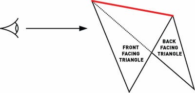
Edge detection techniques are fundamental to non-photorealistic rendering algorithms. Two of the fundamental algorithms used in non-photorealistic rendering algorithms are silhouette edge detection and crease edge detection. The silhouette edge is the part of a model where the front facing triangle borders a back facing triangle. A crease edge is found where the angle between two front facing triangles is beyond a certain application-defined threshold.
In the past decade, many different techniques have been used to detect and draw these edges. Each method has its strengths, as well as room for improvement, but none of them provides an accurate representation of edges detected and created entirely on the GPU.
This article discusses a GPU-based implementation of edge detection and inking using the geometry shader model available in DirectX 10 capable hardware and provides a walk-through of the geometry shader implementation and the additional capabilities it provides.

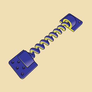
This model of a spring has a simple Gooch shading applied, along with the edge detection techniques in this paper.
Edge-based inking (see Marshall in References) uses a preprocessing step to build a unique edge list for the model being evaluated on the CPU. Each triangle is decomposed into edges, which are then stored in a hash table. The table can be compacted by discarding all edges that are not unique.
Each edge contains information about the vertices on the edge, as well as a flag entry. This flag entry identifies the edge as being a silhouette, crease, or other type of edge and is initially set to an arbitrary value and updated at runtime. The face normals must also be computed for each triangle and stored in the edge list in this preprocessing step.
The runtime portion of this technique begins with updating the face normals (if using an animated model). Computation of the view vector takes place in this step, and the edges are tested using the view vector (V) and the face normal (N1 and N2). This process will determine if they are silhouette edges by testing to see if the sign of the cosine of the angles between the face normals and view vector differ:
[N1XV] X [N2XV) lesser than or equal to 0.

A silhouette edge is an edge shared by a front and back facing polygon.
After the silhouette edges are found with this technique, the edge flags are updated to label the edge as a silhouette edge. The next step is to detect crease edges by testing to see if the cosine of the angle between two adjacent triangles joined by the edge being tested is above a certain threshold. If an edge is detected as a crease edge, the edge flag is set to indicate this, testing with the equation:
|N1XN2| lesser than or equal to cos?
To determine whether to draw or ink an edge, iterate over the edge list and render only the edges with the silhouette and/or crease edge flag set to true. The render state should be set up so that the line thickness is of a higher value than the default; so the edge is visible and of a visually appealing width.
This method requires a graphics API that allows line thickness to be set explicitly for visually appealing results. Unfortunately, it creates a challenge for game developers since Direct3D does not allow for the line thickness to be explicitly set by the application.
To get around this, a different technique was offered for Direct3D: programmable vertex shader inking. Shader inking is possible with both the Direct3D and OpenGL APIs and is dependent only on having a programmable vertex shader. The dot product of the vertex normal and the view vector are used to index into a one-dimensional texture, which then gives a varying thickness line around the model's silhouette edge.
This technique is fast, as it runs entirely on the graphics card (see Marshall in References), and it offers some stylization of the lines as the polygons on the edge show varying thickness along the silhouettes, depending on the polygon's angle with respect to the view vector.
Unfortunately, using shader inking has at least three drawbacks. For one, it uses only the vertex normal. Second, it can miss certain silhouette edges. And third, the varying edge thickness is very difficult to control.
Since DirectX 10 got its geometry shader, programmers are able to calculate face normals on the GPU, allowing for accurate detection methods for both silhouette and crease edges without the preprocessing step and the bus overhead resulting from frequent CPU to GPU communication. Nvidia devised this application and presented it at Siggraph 2006 (see Tariq in References) with respect to detecting and extruding silhouette edges. Here, we will output new geometry for the edges, applying strict control over their thicknesses.

The HLSL implementation of the detection and extrusion algorithm for silhouette edges is shown.
The first step is to create a mesh with adjacency information. This is done by creating a vertex buffer with three vertices per primitive, and then creating an index buffer containing the adjacent vertices in the proper winding order. The primitive-type triangle with adjacency must be declared in both the host code and the geometry shader constructor. As a result, the geometry shader gets access to vertex information from three triangles: the primary triangle, and the three adjacent triangles for a total of six vertices.
With this information we should test the primary triangle to see if it's front-facing by calculating the dot product of the face normal and the view direction. If the result is less than zero, we have a front-facing triangle and need to check whether it contains a silhouette edge (see Gooch et al. in References). This test is performed in world space coordinates. (See Listing 1.)
Listing 1
float3 faceNormal = normalize(cross(
inputVertex[2].position - inputVertex[0].position,
inputVertex[4].position - inputVertex[0].position)
);
float3 viewDirection = -inputVertex[0].position;
float dotView = dot(faceNormal, viewDirection);
if(dotView < 0)
//The triangle is front-facing, check to see if it contains a
//silhouette edge.
We test the three vertices containing an adjacent triangle with the shared edge by taking the dot product of the adjacent triangle's face normal and the view direction. If the result is greater than or equal to zero, we have a silhouette edge. To detect a crease edge, we simply calculate the dot product of the primary triangle's face normal with each adjacent triangle's face normal. If the result is less than an application defined threshold value, we have a crease edge.
Once we know we have an edge, we need to create the extruded geometry. We do this by creating fins in the direction of the normal of an application-specified constant thickness, then loop twice over each vertex, and simply replicate the vertex and transform it in the direction of the normal vector for each vertex that exists as a point along the silhouette edge. (See Listing 2.)
Listing 2
//The face normal of each adjacent triangle is calculated in //order to test whether it contains the adjacent edge. The //prefix vs designates view space coordinates, the prefix ws //indicates world space coordinates and the prefix ps //indicates perspective correct world view space //coordinates.
float3 wsAdjFaceNormal =
normalize(
cross(normalize(vertA.wsPos - vertC.wsPos),
normalize(vertB.wsPos-vertC.wsPos)));
float dotView =
dot(wsAdjFaceNormal, vertA.wsView);
if(dotView >= 0.0)
{
for(int v = 0; v < 2; v++)
{
float4 wsPos = vertB.wsPos +
v * float4(vertB.wsNorm,0) * g_fEdgeLength;
float4 vsPos = mul(wsPos, g_mView);
output.psPos = mul(vsPos, g_mProjection);
output.wsNorm = vertB.wsNorm;
output.EdgeFlag = SILHOUETTE_EDGE;
Stream.Append(output);
}
for(int v = 0; v < 2; v++)
{
float4 wsPos = vertC.wsPos +
v * float4(vertC.wsNorm,0) * g_fEdgeLength;
float4 vsPos = mul(wsPosition, g_mView);
output.psPos = mul(vsPosition, g_mProjection);
output.wsNorm = vertC.wsNormal;
output.EdgeFlag = SILHOUETTE_EDGE;
Stream.Append(output);
}
Stream.RestartStrip();
}
A crease edge can be either a ridge or valley edge. A ridge edge has an angle between the face normals that is either equal to or greater than 180 degrees, while a valley edge has an angle less than 180 degrees.
Since we extrude along the vertex normal, z-fighting may occur when we have valley edge with an angle near 90 degrees because the vertex normal in this case is coplanar with the face of the adjacent triangle. In order to solve this problem, we apply a z-bias to the affected edge by transforming the geometry a distance epsilon in the direction of the camera. (See Listing 3.)
Listing 3
for(int v = 0; v < 2; v++)
{
float4 wsPosition = Vertex.wsPosition +
v * float4(Vertex.wsNormal,0) * EdgeLength;
float4 vsPosition = mul(wsPosition, WorldToView);
vsPosition.z -= ZBiasEpsilon;
output.psPosition = mul(vsPosition,
ViewToProjection);
output.wsNormal = vertB.wsNormal;
output.EdgeFlag = CREASE_EDGE;
Stream.Append(output);
}
The final step is to designate an edge type similar to the edge flag described earlier, by setting an enumeration in the pixel shader input struct stating the edge type. This will enable us to color the edge and allows for explicit stylization and lighting based on edge type.

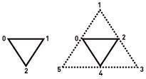
The three steps in the extrusion of an important edge: identifying the edge itself [left]; walk the vertices and output one in the original position and another in the direction of the normal a distance T as defined by the user [middle]; and create a new geometry [right].

Coplanar geometry drawn in a second pass results in z-fighting. To address this we transform the vertices a small distance epsilon toward the viewer [exagerated in figure for illustrative purposes] giving a much more visually appealing result.
The choice to extrude geometry in the direction of the vertex normal gives a visually appealing silhouette edge in most cases. However, there is a visible gap if the model causes abrupt changes in the direction of extrusion when walking the vertices as they near a hard edge.
A hard edge is an edge where the triangles forming the edge share vertices with orthogonal normals. For example, a cube contains hard edges along its entire silhouette. A visual gap is noticeable at the transition point where the geometry changes from a silhouette edge (which is not also a hard edge), to a silhouette edge (which is a hard edge).
If a hard edge is present and inked as well, it occludes the transition point in most views. In practice, this visual gap is likely to be of little importance since both crease edges and silhouette edges are inked in most non-photorealistic rendering applications. The gap effect increases as the line thickness increases-it's not visible when the line is of typical thickness but is quite obvious when the thickness is large.

Increasing the line thickness increases the visible gap as the coincident vertex of a hard edge abruptly changes direction.
Aligning the fins to be perpendicular to the eye, instead of extruding along the normal, should also hide the discontinuity, although it would introduce z-fighting since there's no guarantee the silhouette would be rendered on a different plane than the geometry. One way to handle this predicament is to bias the z component of the silhouette's vertex position by a factor epsilon.
It may also be worthwhile to explore implementing a more complex edge constructed as a closed manifold surface. While this would take significantly more resources, seeing as the amount of additional geometry required would increase greatly, it would allow for very complex stylization of the edges.
Silhouette and crease edge detection and extrusion on the GPU gives us several possibilities for future work. Stylizing the edges so they look similar to edges drawn by a human artist could also be possible within the geometry shader.
It's possible to do some quick real time edge stylization by biasing the extrusion direction or applying texture maps to the new geometry, but more advanced techniques could also be used in order to create stroke styles, ink styles, varying width, "shock" silhouettes, "dashed" silhouettes, "shattering" silhouettes, and other techniques in real time with DirectX 10 using the new capabilities of Direct3D 10 and Shader Model 4.0.
Joshua Doss is part of the advanced visual computing team in the Intel Software Solutions Group. Send comments about this article to [email protected].
The author acknowledges support and review by Adam Lake, Matthew Williams, and David Bookout at Intel. Digital assets were designed by Jeffery A. Williams at Intel.
Marshall, Carl S. "Cartoon Rendering: Real-time Silhouette Edge Detection and Rendering," in Game Programming Gems 2. Hingham, Mass.:
Charles River Media, 2001.
Akenine-Moller, Tomas and Haines, Eric. Real-time Rendering Volume II, Wellesley, Mass.: AK Peters Ltd., 2002.
Lake, Adam, Marshall, C., Harris, M., and Blackstein, M. "Stylized rendering techniques for scalable real-time 3D animation," Non-Photorealistic Animation and Rendering archive, Proceedings of the 1st international symposium on Non-photorealistic animation and rendering. Annecy, France: ACM Press, 2000.
Gooch, Amy et al. "A Non-Photorealistic Lighting Model For Automatic Technical Illustration," in NPAR 2000, 13-20, 1998.
Tariq, Sarah at NVIDIA 2006. "DirectX10 Effects," Siggraph 2006.
http://developer.nvidia.com/object/siggraph-2006.html
Read more about:
FeaturesYou May Also Like