Trending
Opinion: How will Project 2025 impact game developers?
The Heritage Foundation's manifesto for the possible next administration could do great harm to many, including large portions of the game development community.
Featured Blog | This community-written post highlights the best of what the game industry has to offer. Read more like it on the Game Developer Blogs or learn how to Submit Your Own Blog Post
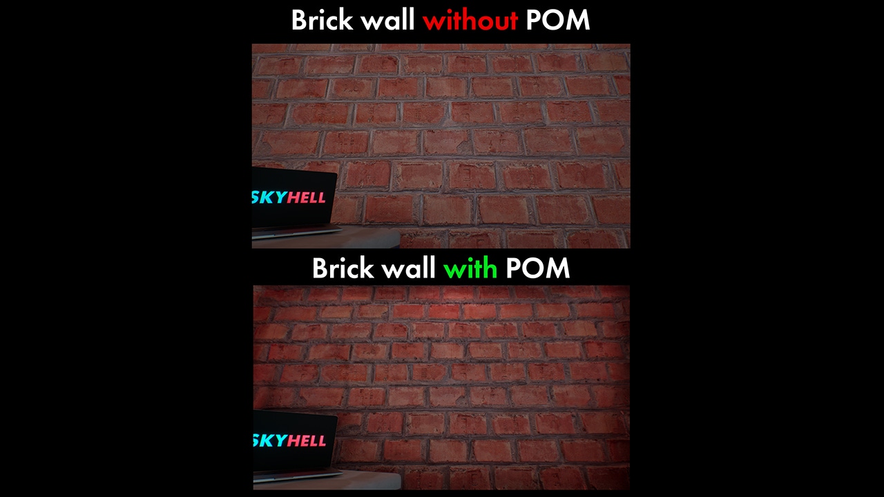
We create for our materials Parallax Occlusion Mapping (POM) in UE5. It's a complex texture-based approach to add more details for objects.
August 30, 2024
It’s still a problem understanding such a complex approach in materials like POM and we’ll try to deeply understand how to use POM and as short as possible. Also we’re going to explain what each node does and why we use each one of them.
Let’s start with what materials are in Unreal Engine? Materials in Unreal Engine define the surface properties of the objects in your scene. A material is something like a "paint" that defines the visual appearance of an object.
Now what is POM? Parallax Occlusion Mapping (POM) is a complex texture-based approach to add more details for meshes. With POM we get more depth visually than we could get just with Normal maps, because we get three-dimensional shapes without adding any additional vertices to meshes. POM uses Ray Tracing to find the correct offsets at each point.
So why is Parallax Occlusion better than making subdivision to meshes?
It’s faster than modeling since you can put it on any mesh;
Easy to set - you can do it with all textures if they’re correctly made.
But there are also some things that you should remember:
POM adds texel height data, separately from the texel normal data;
Each fragment of data is ray-traced on the GPU to determine the correct visual result, resolving all of the above limitations. This gives an exceedingly realistic result under many viewing conditions, at the expense of substantial GPU time;
We still use the same textures that we would. The difference is we also add a displacement map and a few more nodes to our material;
POM doesn’t really work with overlapping UV and can look bad if you have wrong UV;
On low scalability POM won’t be visible at all. You should have AT LEAST medium scalability;
POM is a complex function and we need a lot of nodes that should be also correctly configured, otherwise we’re going to get artifacts;
POV doesn’t work very well with shadow maps, so PROBABLY you have to untick “cast shadow map” for a mesh to which you have given a POV material.
So let’s create a POM material. First, let’s create a material. Press the right mouse button in “Content browser” and pick “Material”, now you should name it. Since it will be a master material, let’s name it M_POMbricks or MM_POMbricks. The difference between “Master Material” and “Material Instance” is like a parent to a child in programming. If a parent has some values a child will get them too, but a change of values of a child won’t affect a parent. The connection between them is called a “Parameter”.
We’ve got now a completely clean material and we need textures. We can make our own textures, but our main subject is POM , so let’s press the right mouse button on “Content Browser” and pick “Add Quixel Content”. Find a brick material. In my case it’s “BRICK WALL”. Download it.

After downloading it, open the material that we created before by pressing the left mouse button twice. To have these textures, you have to select the textures of “BRICK WALL” and move it to the Material Graph. Then you should connect them all like in the screenshot below.

The texture with usual colors without any information about light (Albedo) belongs to “Base color”, it gives colors that we need to see in a brick wall in this case. The blue texture belongs to “Normal”, because it gives depth. But the yellow texture that we call “ARD” texture differs from others, because it has a few textures inside in different channels, so we’re going to use some of them. ARD = Ambient occlusion + Roughness + Displacement, that’s why we connected like what’s on the screenshot.
Now let’s create more nodes so we could finally have a POM effect. To create a node press the right mouse button inside of the material graph and write the name of your node. Or press the palette and find the nodes that you need. In the screenshot there are names for each node.
Constant - is a number that we’re going to need to give a numerical value. It’s a little green node. Press the right mouse button and type “Constant”, then press the left mouse button on it. Names of other nodes you can see in screenshots below.


Let’s continue. You see that constante nodes have different names in the screenshots? It’s because they’re not just nodes, they’re Parameters. Now you have to press the right mouse button on them and press “Convert to Parameter”, then you name them like in these screenshots.
Now let’s explore each node. What does each of them mean?

1)Channel (it’s called so because we named it like that after making this node a Parameter) - is a four-vector constant, to create it you need to write not just “constant”, but “constant4vector”. As we wrote before, this node controls which channel is going to be provided to ParallaxOcclusionMapping. If you remember what we wrote about ARD, then you can guess that we’re going to use “B” channel, which means we have to make it completely Blue, so it should be 0,0,1,0. Also we used the node “Append”, because ParallaxOcclusionMapping expects us to give value of constant4vector (that’s why there’s written V4) and since four-vectors constantes have Alpha channel we give the color (B channel) and alpha.

2)Texture Coordinate controls scaling of the texture. Create another node and connect it to “Multiply” (this node multiplies two connected values), create another node and connect it too. Now you can scale it. We need texture coordinates and the scale depends on the scene you’re creating.
3)Height Ratio (Parameter of one-vector constant) - controls values of our height map, in other words controls how much POM this material will be. We will write 0.3 as a default value and we’re going to change it in a material instance that we’re going to create, because everything depends on the textures that we use.
4)Min Steps and Max Steps - Values for making POV smooth. The more steps we have, the more smooth it becomes, it’s like the modifier “Subdivision” in Blender.

As you see we connected ParallaxOcclusionMapping to the textures, but we also connected “Pixel Depth Offset” of both nodes. We did it because otherwise we won’t have any POV effect. But again as I mentioned before, since we use Pixel Depth Offset, most likely you should turn off “Cast shadow” on actors on which we’re going to use our materials since they don’t work together very well.
We now understand why we created such nodes for the POM effect. Keep in mind that Material Instances with Parameters help us in making materials and this case shouldn’t be an exception either.
In the end of this article it would be great to add a few more things that could help you:
Texture resolution affects memory and bandwidth. They will cause lag and freezes. How you handle resolution depends totally on you;
If you get the warning “The current material has compilation errors, so it will not render currently in feature level SM6”, then you probably forgot to make the node Constant4Vector (Heightmap on images in this article) a Parameter;
Written by Alexander Mukhitdinov, game developer of Skyhell, mentor and co-founder of Cube of Skill. Date - 26th August, 2024. Uzbekistan. [email protected]
You May Also Like