Trending
Opinion: How will Project 2025 impact game developers?
The Heritage Foundation's manifesto for the possible next administration could do great harm to many, including large portions of the game development community.

Featured Blog | This community-written post highlights the best of what the game industry has to offer. Read more like it on the Game Developer Blogs or learn how to Submit Your Own Blog Post
A short discussion about how I went about implementing the physics of ropes in Contraption Maker.

Note: I orginally posted this on my blog a couple of weeks ago.
Contraption Maker (CM) is a sandbox physics game that I developed along with Spotkin;. It was built using a modified version of the Loom Engine, along with a few different libraries/components including cocos2dx and Chipmunk. After going through Steam's early access program, the full game was released on Steam in the summer of 2014.
Getting realistic ropes working required tackling several different problems. It was mostly traveling development paths that others have already blazed and then making whatever adjustments were needed for my specific needs. This is just a quick overview of how I went about implementing them in CM and some of the potholes I hit along the way.
The first decision made was exactly how much of a rope's behavior I was going to model. Deciding exactly what elements or rope behavior to implement involved trade-offs affecting both performance and also design. For example, in their final incarnation, the ropes don't collide with anything. So their only game play function is to transfer forces between the parts attached to either end. This was both a game design and a performance (speed of execution) decision. The performance was better because the code didn't have to calculate all the collision and physics needed for the whole length of the rope cutting down drastically on the calculations needed.
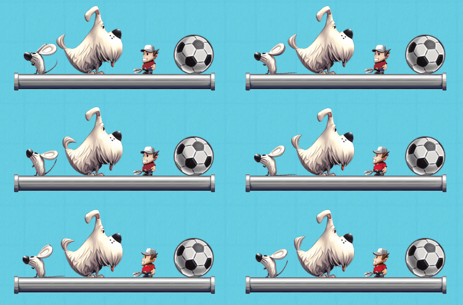
This is fairly typical in the craft of game design and development in that you are always making various trade-offs. The relative sizes of the little guy, the dog, the mouse, and the soccer ball are game design decisions that bent reality for better game play possibilities.
I didn't use the built-in ropes in the Chipmunk physics engine. The Chipmunk engine doesn't have built-in ropes – easy decision. It does have a whole bunch of different types of constraints though, so my first thought was to use those to implement ropes. So browsing through the available constraints, using a slide joint for the two ends of the rope seems obvious. Maybe use the spring joint for all the points between the rope endpoints?
Speed of execution was a big concern. People playing CM are going to be able to create huge contraptions which could include ones with very many long ropes. Okay, first thoughts, rather than use Chipmunk's general spring constraint, I'll write a tighter custom spring-like routine specifically for our ropes with a focus on minimizing calculations needed and still simulate a rope in a way that looks and behaves realistically. I sketched out this fairly simple idea before writing any code.
The slide joint constraint keeps two point-mass Chipmunk bodies within a specified range of each other. It is given the two bodies to constrain along with a minimum and maximum distance that the bodies should be from each other. Therefore each end of a rope is attached to a body – either to a body of a CM part or, in the case of an unattached rope end, to a physics body at end of the rope.
The slide joint is perfect for handling the behavior of the two endpoints of a rope. For ropes in CM the minimum distance is always set to zero and the maximum distance is the length of the rope. In the simple setup pictured below, a slide joint constraint is attached to the center of the static body of the hook and also attached to an offset of the center of dynamic body of the block.
Okay, great, first bit done, easiest code to write is code that someone else has already written. Now it's time to take care of simulating the rope between the two endpoints - how it moves when it is slack. Note below that you can see how the rope passes right through the brick wall. As mentioned above, the ropes don't collide with any other parts or with itself. My only concern with the internal rope movement was that it appear rope-like; it didn't affect physics outside of itself. To do that I needed to break the rope into individual segments and then make move in a rope-like way. You can see each of the individual segments as purple dots in the picture below.
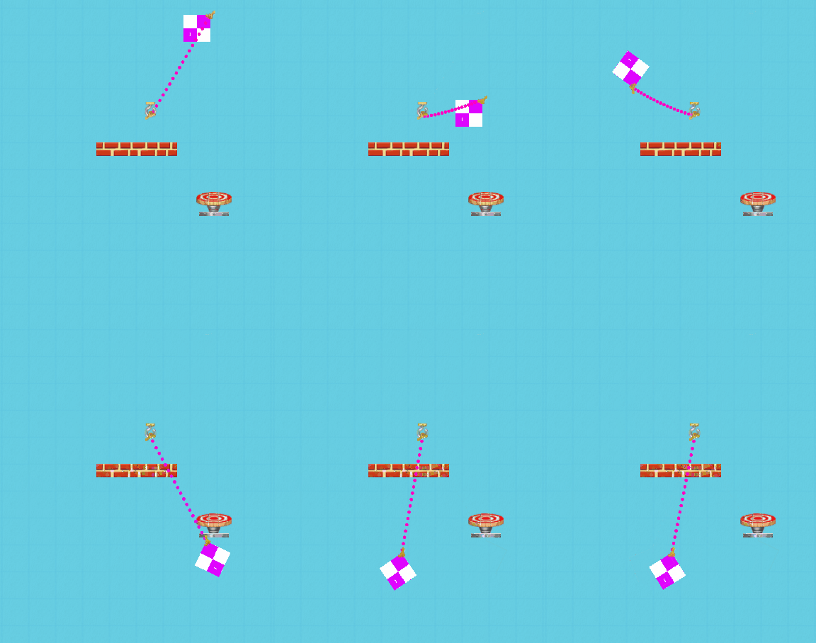
To make the display look like an actual rope it is then just a matter of replacing the purple dot artwork with rope segment artwork. The art is rotated to seamlessly join the individual segments. Here is the same setup with the purple dots replaced with rope segment art:

Once I sat down and thought for a a while, I decided to go with verlet integration to take care of all the internal segments of the rope. It solves the problem very nicely and the code is very fast to execute. The process is:
Use each segment's current and previous location to determine velocity
Add this velocity to current segment location to get new location
Add in gravity (steps 1-3 are in first code excerpt below)
Run multiple passes per time-step working towards getting neighboring rope segments a fixed distance apart. This is an iterative process where the more iterations the better the solution. A trade off between execution speed and robustness of solution. CM used seven iterations per time-step. (this is done in the second code segment below)
These four steps are explained and illustrated very well here: http://blog.2and2.com.au/?p=883
This is the code that applies velocity and gravity to each rope segment once per time-step.
IMPORTANT CODE NOTE: For reasons I mentioned in The Butterfly Effect, all the physics calculations are done using integers instead of floats so the code listed above is using int(s) instead of floats. There is some bit-shifting going on to keep the numbers within my fixed point number system where 65536 is equal to 1. The code is very simple:
for (int i=0;i<;=lastIndex;i++)
 {
    // Gravity (assuming only in y axis)
    CMRopeSegment *seg = static_cast<CMRopeSegment*>(mSegments->objectAtIndex(i));
    seg->mY -= gravityY;

    // Verlet
    int temp = seg->mX;
    seg->mX += (seg->mX - seg->mOldX);
    seg->mOldX = temp;
    temp = seg->mY;
    seg->mY += (seg->mY - seg->mOldY);
    seg->mOldY = temp;
 }
And here is the code that makes multiple passes per time-step through all of the rope segments
// Run a few iterations to process all the links (defaults to 7 steps)
 for (int step=0;step<mIntegrationSteps;step++)
 {
    CMRopeSegment *prevSeg = static_cast<CMRopeSegment*>(mSegments->objectAtIndex(0));
    for (int i=1;i<mNumSegments;i++)
    {
       CMRopeSegment *seg = static_cast<CMRopeSegment*>(mSegments->objectAtIndex(i));
       int dx = seg->mX - prevSeg->mX;
       int dy = seg->mY - prevSeg->mY;

       // Custom integer version of square root function
       int dist = tmSqrtShiftedInt32(dx * (tmInt64)dx + dy * (tmInt64)dy);

       // Keep in a sane range to prevent divide by zero from happening
       if (dist < 128)
          dist = 128;

       seg->mLength = dist;

       int delta = seg->mAdjustedLength - dist;
       tmInt64 percent = (delta * FLOAT_TO_INT64(0.7f)) / dist;
       int offsetX = (int)INT64_SHIFT_DOWN(dx * percent);
       int offsetY = (int)INT64_SHIFT_DOWN(dy * percent);

       if (i == 1 && firstIndex != 0)
       {
          seg->mX += offsetX;
          seg->mY += offsetY;
       }
       else if (i != 1 || firstIndex == 0)
       {
          prevSeg->mX -= offsetX;
          prevSeg->mY -= offsetY;
       }
       else if (i != (mNumSegments-1) || lastIndex == (mNumSegments-1))
       {
          seg->mX += offsetX;
          seg->mY += offsetY;
       }

       prevSeg = seg;
    }
 }
Before the verlet integration is run, the slide joint constraint first adjusts the locations of the bodies on either end of the rope. The first and last rope segments are then set to the locations taken from where the slide joint has computed the bodies' locations. These first and last segments are not changed by the verlet integration, only all the segments between these two are changed. The verlet code above is run adjusting all the positions of the interior rope segments and giving us nice rope-like movement, but they transfer no force to the bodies on each end of the rope.
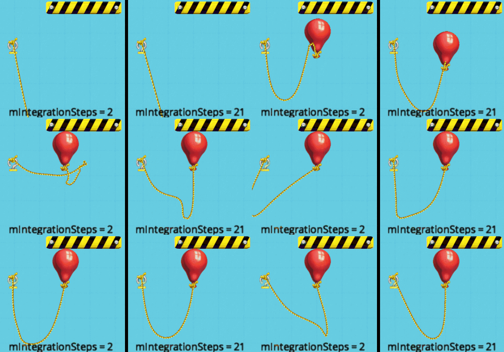
Verlets give “springy” results which can be minimized by increasing the number of iterations run per time-step. Contraption Maker uses 7 iterations per time-step. You can see the difference below using two different iterations Two integration steps take longer to come to rest than the 21 step version.. Not really obvious here, but enough of a problem to be noticeable in the game is integration steps are too small.
The physics of direct rope attachments between two parts is now done. Next up was adding pulleys. There is no pulley support in Chipmunk, but I did find some code written for Chipmunk by Robert Blackwood that was based upon Box2d's pulleys. I took that, modified it to work well with our system and eventually had pulleys working, albeit with some problems I'll mention below. All the physics happens on the two rope segments hanging off of the first and last pulleys. All the parts of a rope that is between two pulleys is treated as a straight line with no physics processed for them. Any slack in the rope will only occur on the parts of the rope off either end of the pulleys.
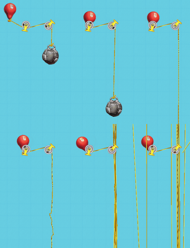
The pulleys almost completely worked, but there was a problem that became very obvious when the bodies on each end of the rope have very disparate masses. This is a typical problem in physics engines where if you have two bodies where the ratio between the two masses is very great the physics can break down. And I mean break down in a very spectacular ways like this:
That is a fairly obvious problem, but there were also problems when the differences in masses were not as great – not as visible as above but still there. The system could get in a state where the forces acting on the bodies were oscillating back and forth causing jitters or slow rope stretching on one end of the pulley system. Problems like this are very hard to track down and fix because there is so much math calculations going on with different forces being applied at different places. Here is an example of the the log output that I would use to track down physics problems:

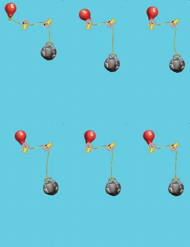
Using the balloon/wrecking ball as a good test case and tracking through what was happening with impulses and cached impulses, it looked like energy was not being lost when the balloon hit the pulley – ah, guess what – it was because the balloon wasn't hitting the pulley – no collision shapes on the pulley. Problem identified - next step problem solution.
In Contraption Maker the pulleys did not collide with anything because this allowed them to be placed so they could overlap with walls and other parts. But this did not correctly resolve the situation like that pictured above where the length of the rope on one end of the pulleys goes to zero. To solve this I added a special collision shape at the point where the rope attaches to the pulley. This ad hoc collision shape on the pulley would then only collide with another ad hoc collision shape at the location where the rope was attached to a part.
Now the part collides with the pulley and the physics system can apply the correct forces on the bodies. Here's the same pulleys system as above but now the balloon correctly collides with pulley. You can see how the balloon bounces off the pulley. Success. All is well in the CM world.
Read more about:
Featured BlogsYou May Also Like